Custom HUD for Subaru WRX with Digital Gauges
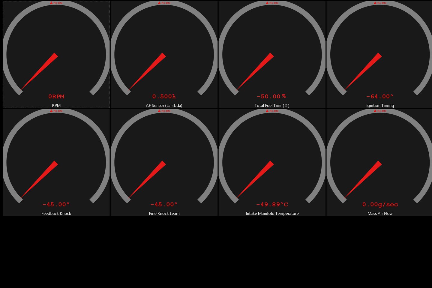
Discover a custom heads-up display (HUD) designed specifically for the Subaru WRX. This innovative project utilizes a Raspberry Pi and Atlas software to provide real-time EFI tuning data and digital gauges, all while allowing for phone storage and infotainment access.
CADAUTOMOTIVEELECTRONICSDESIGNPROTOTYPING
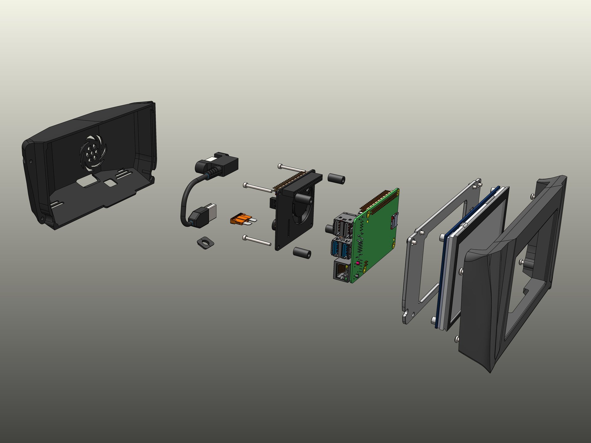
Project Overview
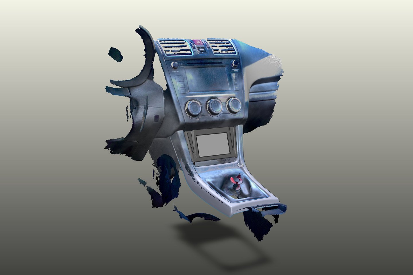
The WRX cubby provides an ideal space for a custom HUD display. The goal is to create a self-contained system that integrates a touchscreen for real-time gauge display using ATLAS software. It also needs to ensure ease of manufacturing and accessibility while maintaining a compact design.


Design Iterations
V1 - CAD DESIGN ITERations
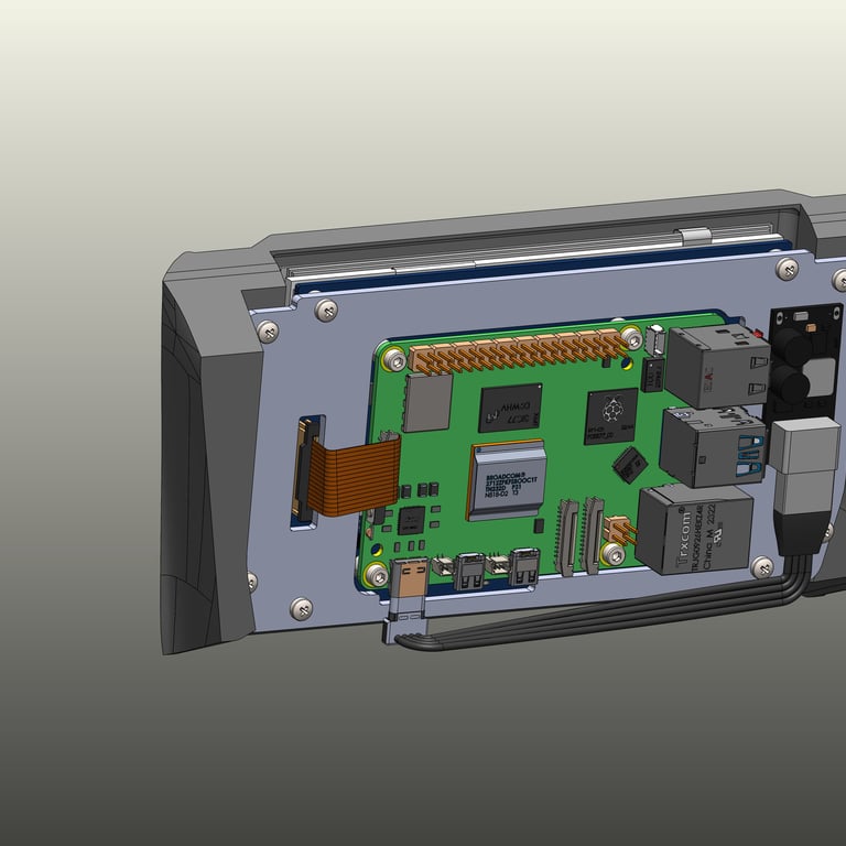
The first version of the design established the front face structure. However, the USB-C power requirement for the Raspberry Pi 5 created space constraints, making enclosure difficult. A buck converter was added to step down 12V to 5V, but this blocked key I/O ports, limiting connectivity for accessories like OBD-2 input. This issue led to a necessary redesign for better component placement.
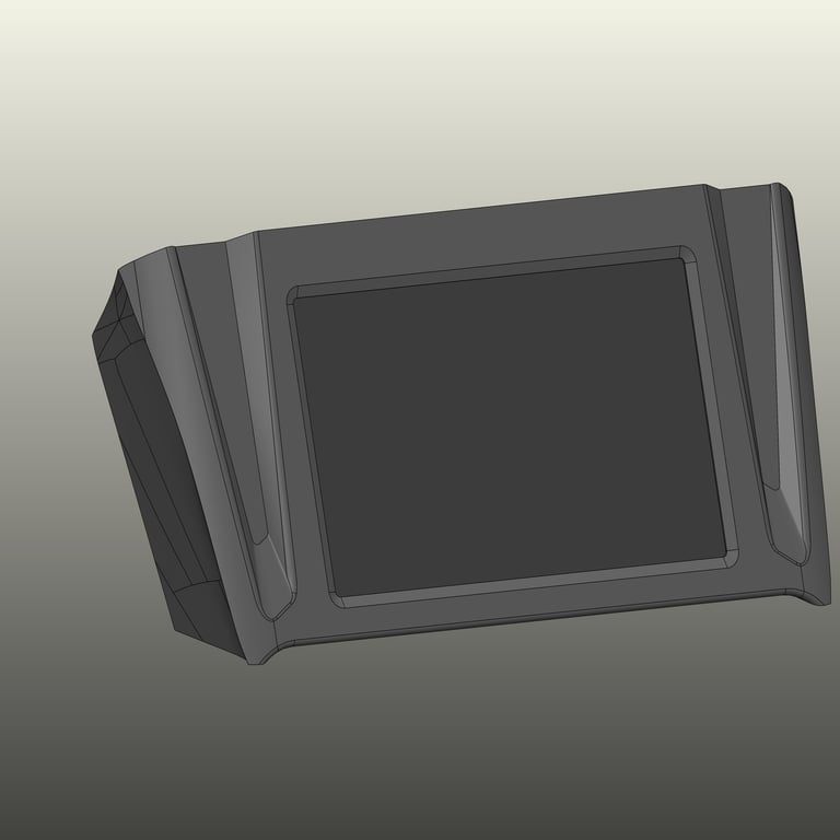
V2
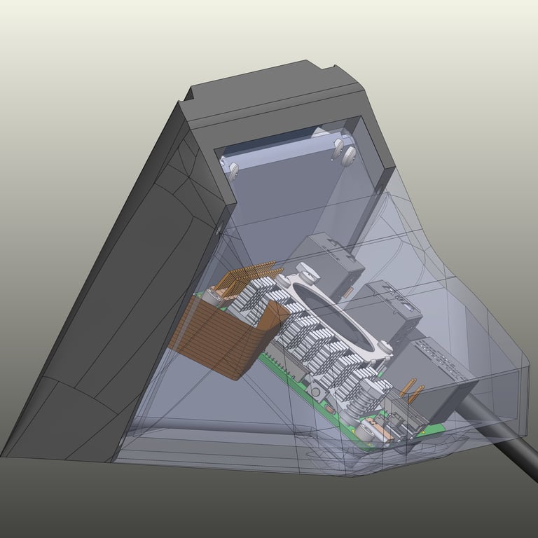
In the second iteration, the Raspberry Pi 5 was repositioned to fit better within the cubby. The buck converter was moved to the top, freeing up USB ports for OBD-2 connectivity. To address heat concerns, a heatsink and fan were added to keep the Raspberry Pi cool, ensuring stable operation in the high-temperature environment of a car interior.
V3
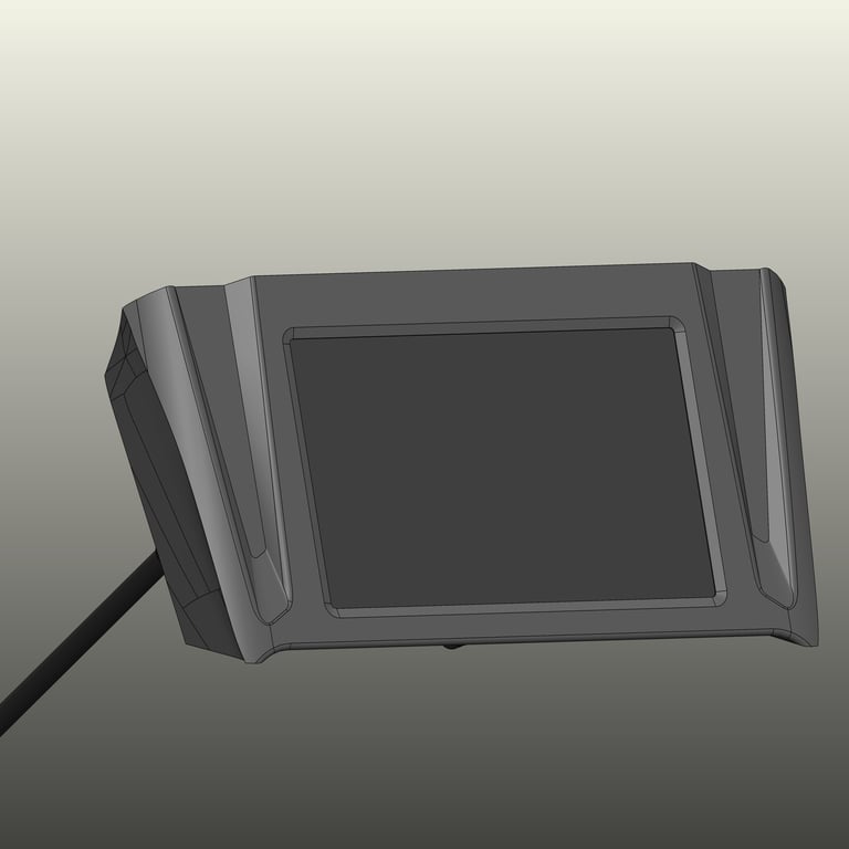
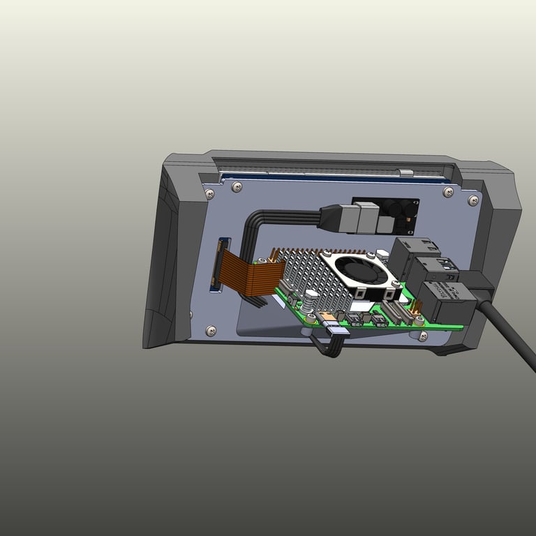
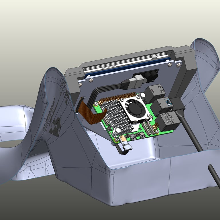
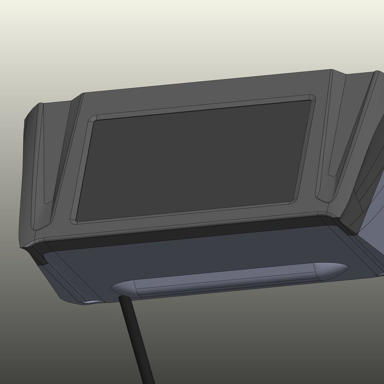
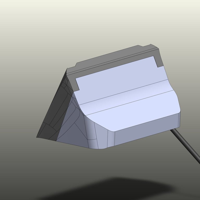
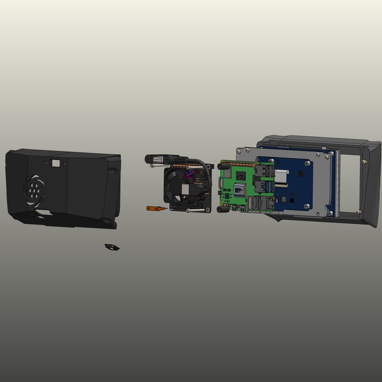
The third version introduced the rear housing, packaging all components efficiently within the confined space. A small bump was added to accommodate heat stake inserts, ensuring strong and durable mounting. Additionally, the vertical mounting plate was optimized for 3D printing without supports, improving print quality and reducing material waste.
V4
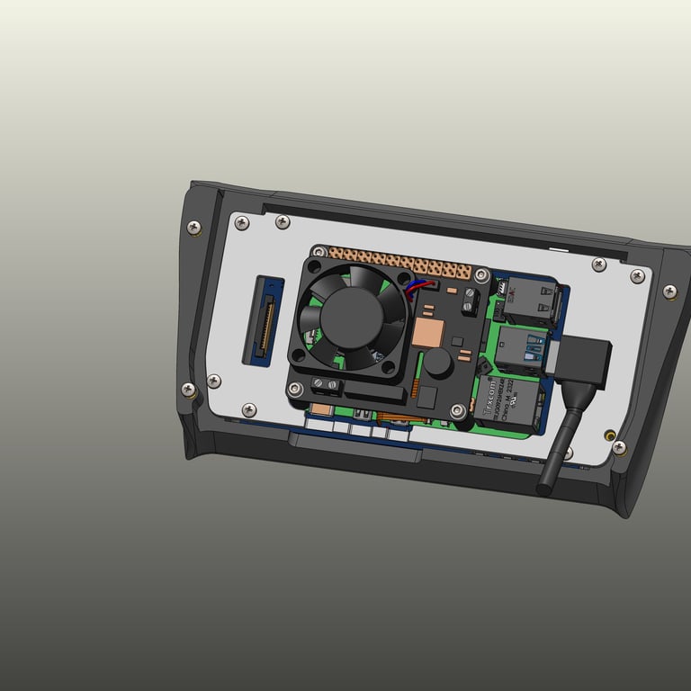
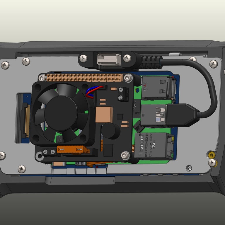
Further refinements came in the fourth iteration, which introduced hidden mounting screws and cable pass-through holes. Cooling was also enhanced with intake and exhaust fans, improving airflow around the electronics. After researching alternatives, the buck converter was replaced with a Raspberry Pi HAT that integrated power conversion and cooling into a single unit. Power conversion was needed since the car supplies 12V and the Raspberry Pi needs 5V. This change significantly reduced the overall footprint, making the design more compact.
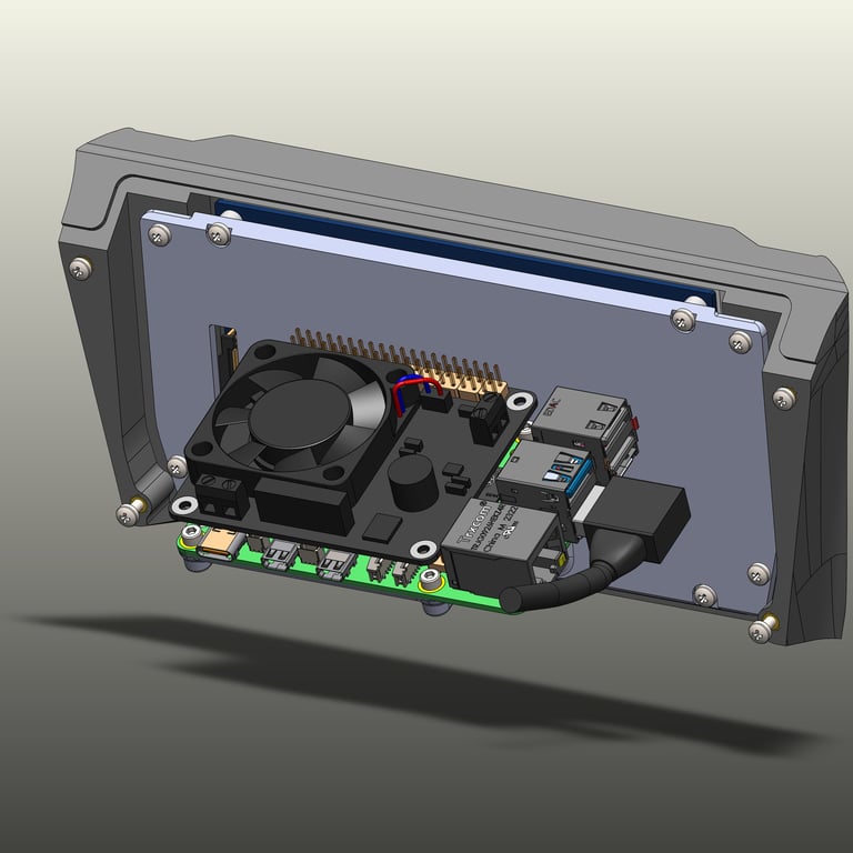
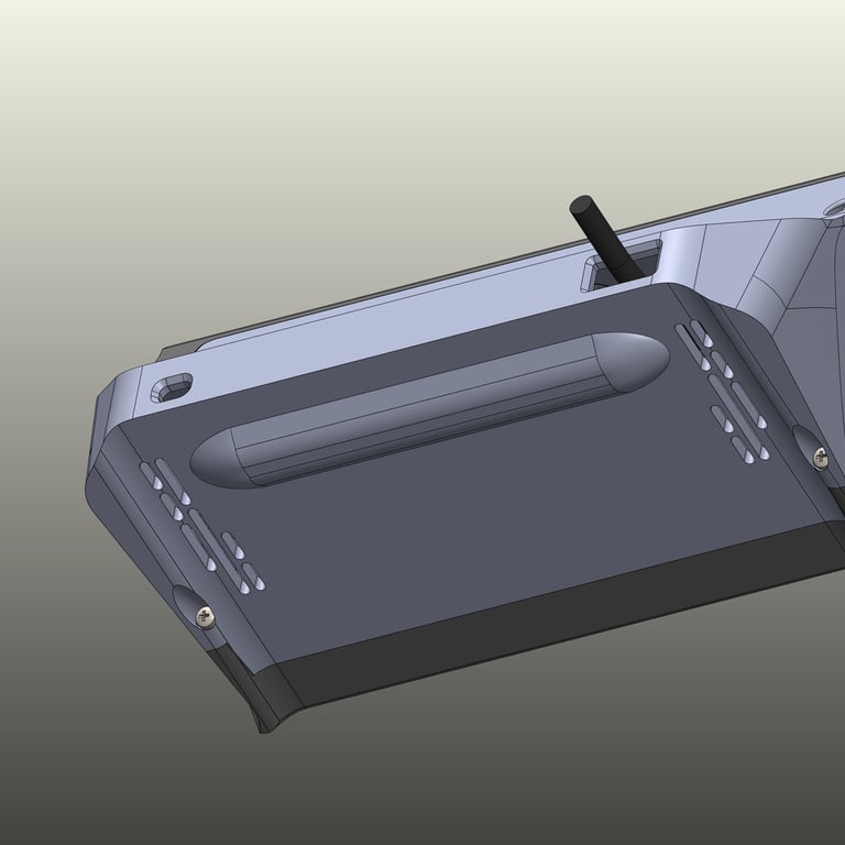
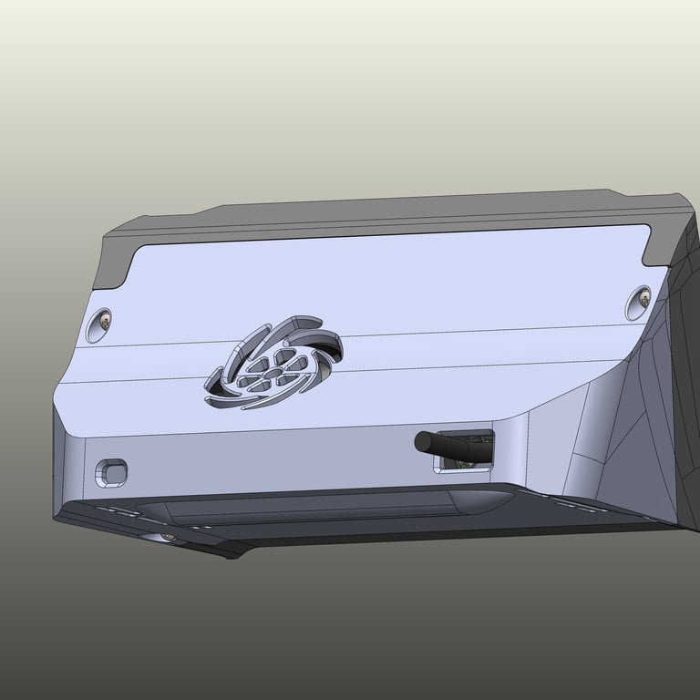
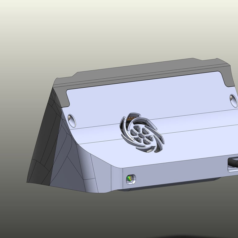
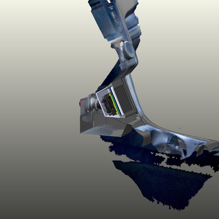
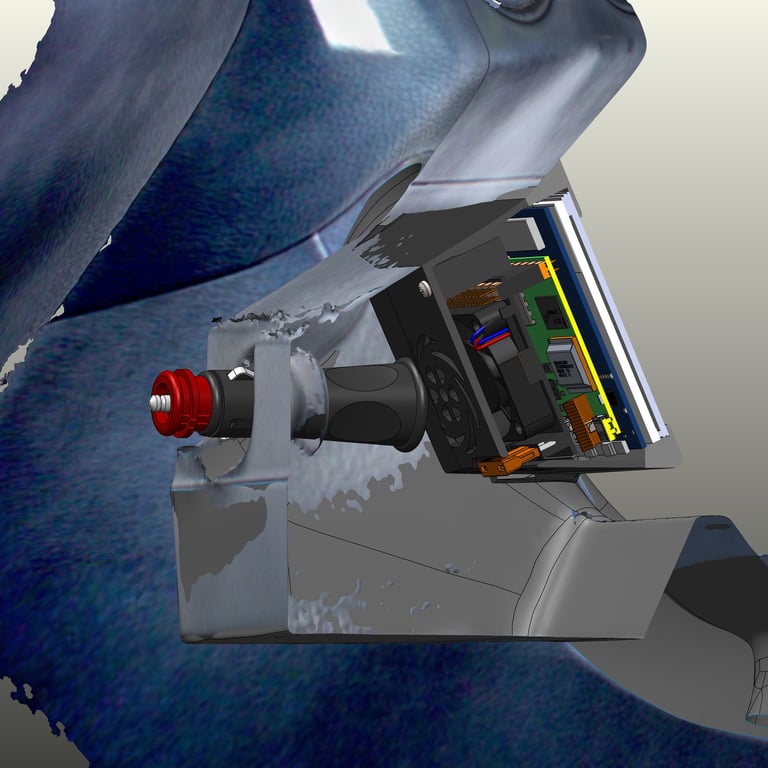
V5
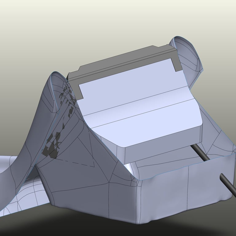
By the fifth version, it became clear that more space was available within the cubby than initially thought. Expanding the scanned area to include more of the dash revealed additional usable space. A new rear housing design took advantage of this extra room, allowing for better packaging of components. The Raspberry Pi was reoriented back into alignment with the display, saving depth and making the assembly more efficient.
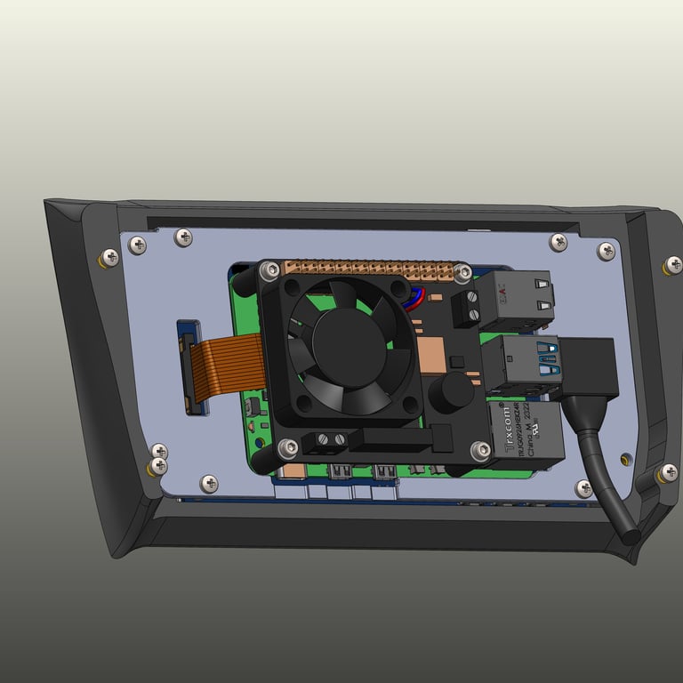
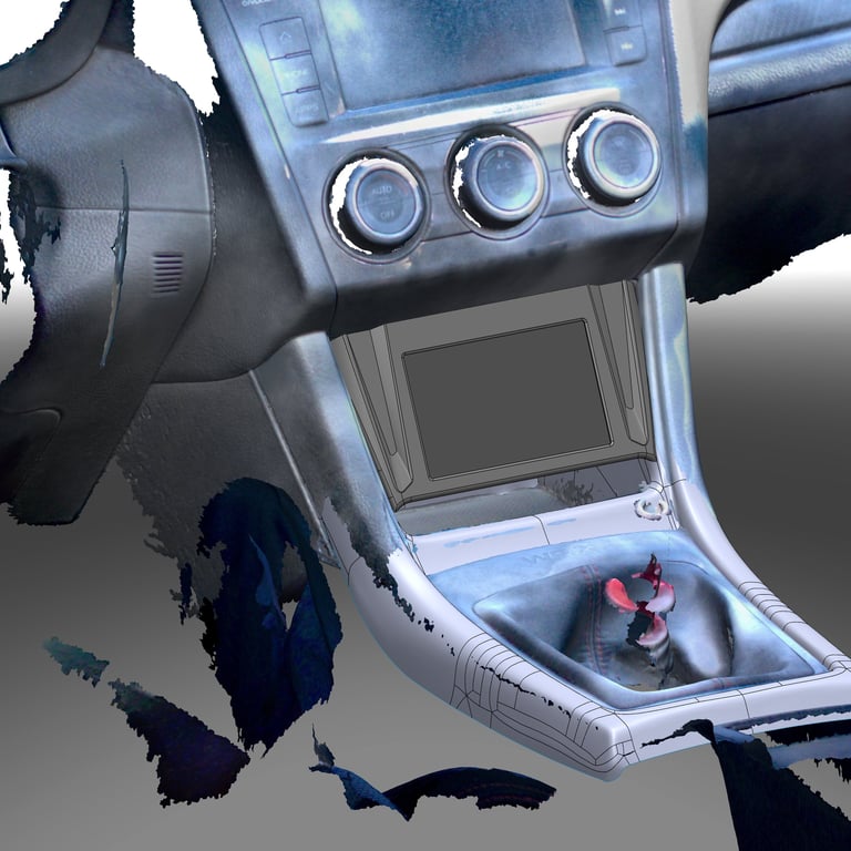
V6
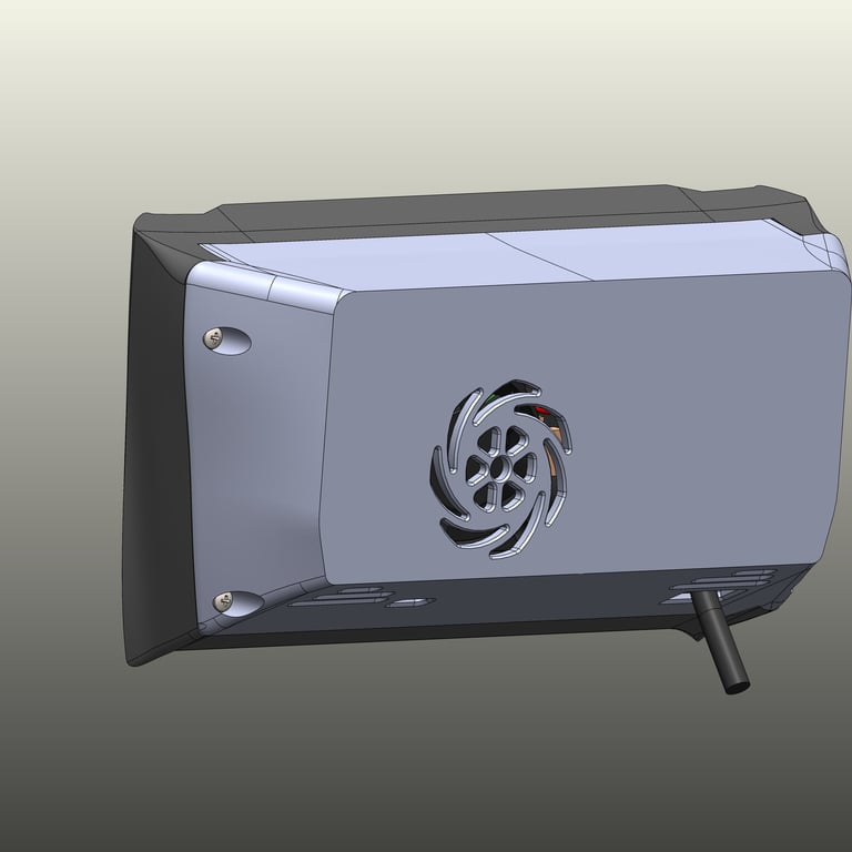
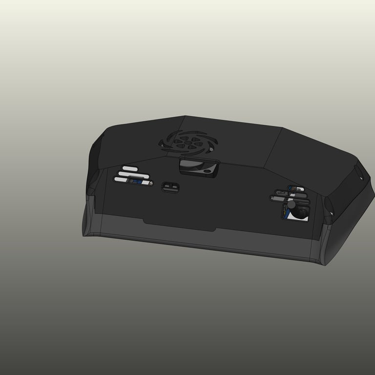
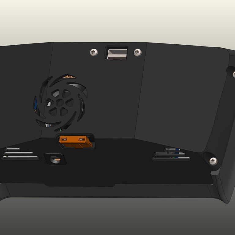
In the latest iteration, a fuse window was added, providing quick visual inspection for maintenance. Additionally, a notch was introduced in both the rear housing and faceplate, allowing easy access to USB and HDMI ports. This improvement ensures that updates and diagnostics can be performed without fully disassembling the unit, enhancing long-term usability.
First Prototype Installed
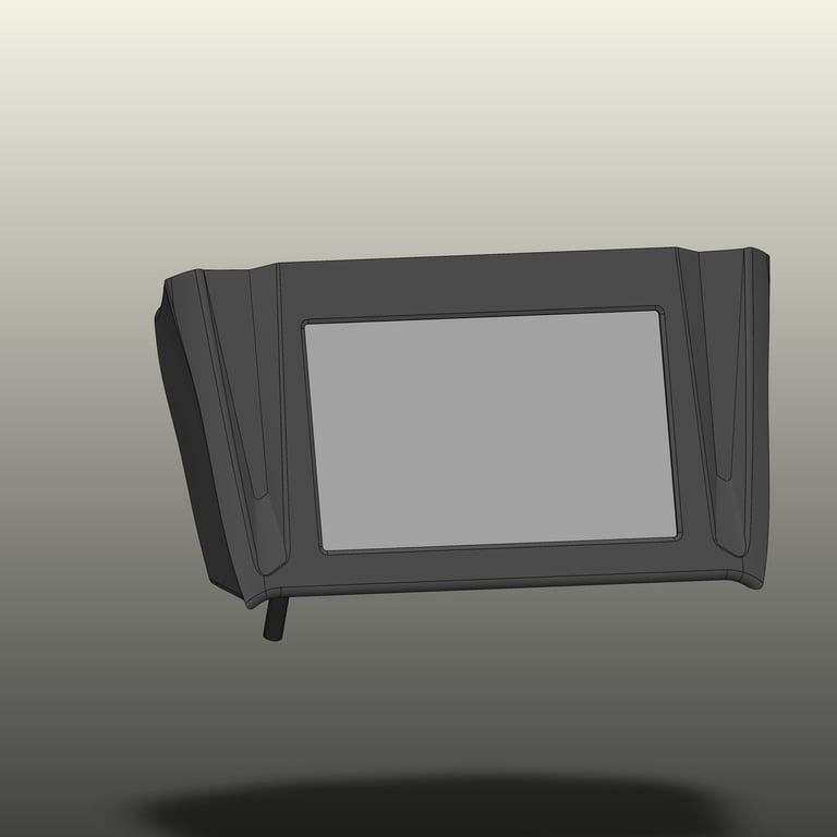
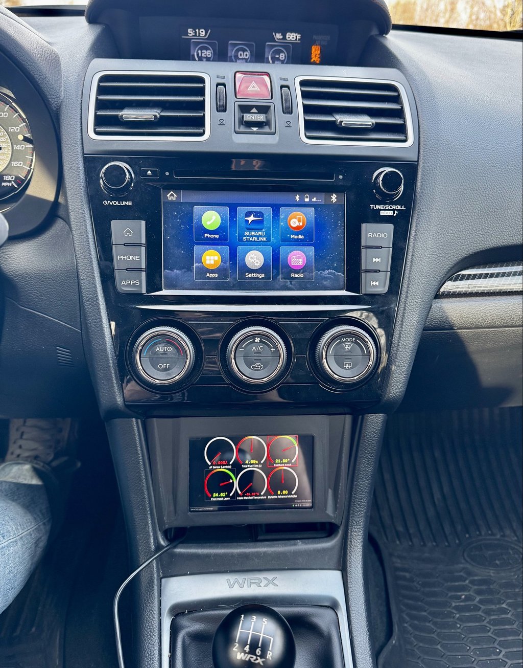
The first prototype has now been installed in the car and functions as expected. The digital gauges work seamlessly, and the overall fitment is excellent. However, after installing it, I quickly noticed a few areas for improvement.
The first issue is with the USB cable running from the Raspberry Pi. It currently hits the bottom of the phone tray/cubby organizer that I designed in a previous blog post. This prevents me from securely storing my phone while using the display. My proposed solution is to relocate the USB input by adding a USB bulkhead to the back of the display housing, allowing external access without interfering with the phone storage. I will update this post with a picture once this change is implemented.
The second issue I encountered is with the heat-stake inserts. Once installed, they slightly reduced the clearance between the front and rear frames, making assembly more difficult. To resolve this, I increased the clearance to ensure the inserts no longer create fitment issues. This small adjustment will significantly improve the ease of assembly.
One of the major highlights of this design is that it requires no hardware or adhesives to mount the HUD securely. Because the frame was created from a 3D scan of the WRX interior, it fits perfectly in place without modification. This showcases the power of 3D scanning in solving complex fitment and packaging challenges, making it a valuable tool for automotive design.

CAD Model with Design Improvements
Here is a CAD model showing the updated design with the USB bulkhead and adjusted clearances for easier assembly. This version also benefits from the improved packaging made possible by the second dash scan. The model now fully utilizes the cubby space without compromising phone storage.
Continuing Updates
This project is far from complete. As I continue to test the heads-up display in real-world conditions, I expect to find more areas for improvement. I will continue updating this blog post with new design iterations and performance improvements. Stay tuned for future updates as this project evolves!
