Designing My First WRX Wing – A Journey from Concept to Prototype
A deep dive into my first custom WRX wing design, covering the design process, challenges, and the final prototype.
DESIGNAERODYNAMICSAUTOMOTIVECADPROTOTYPING
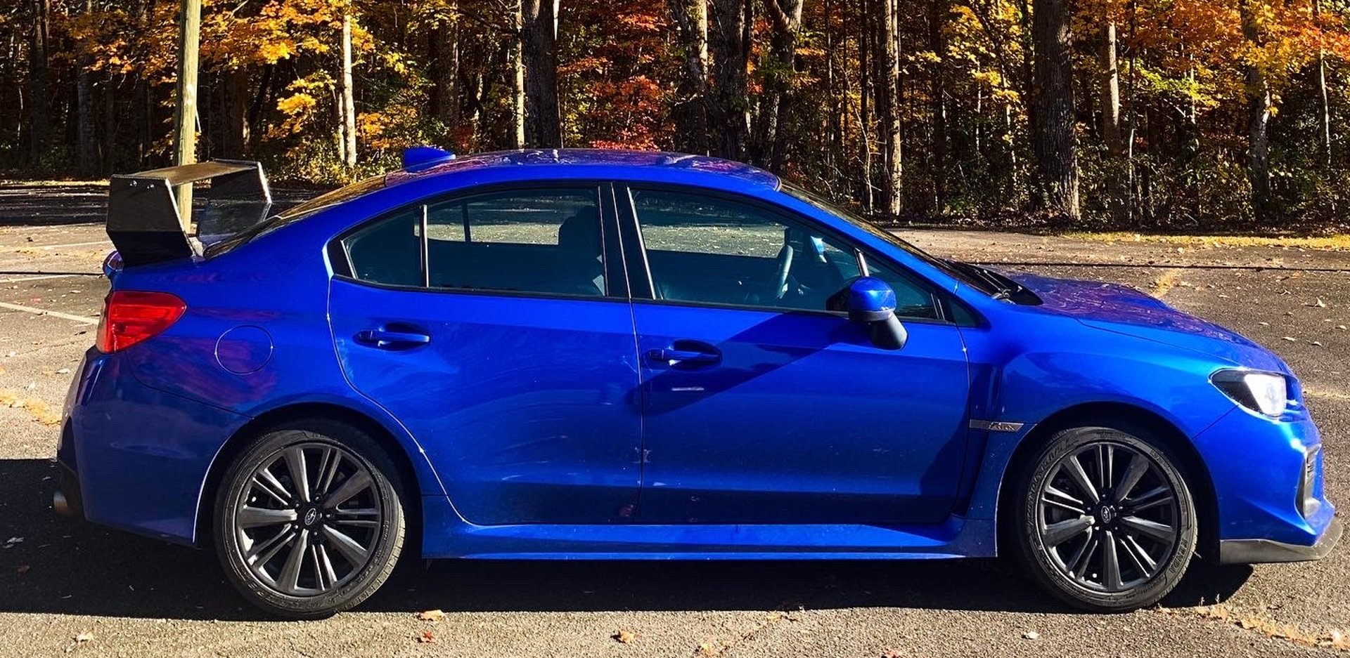
The Inspiration Behind the WRX Wing Design
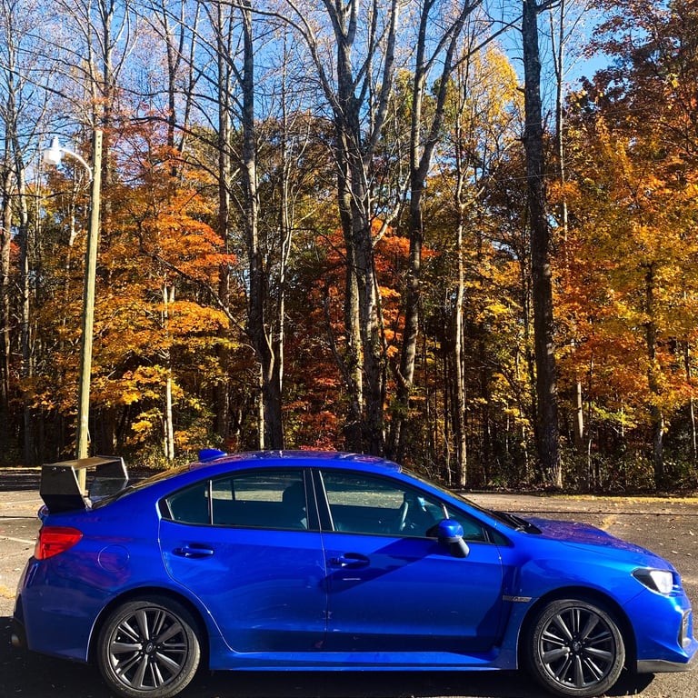
As an engineer and designer, I’ve always been fascinated by the intersection of function and aesthetics. When it came to designing my first WRX wing, I wanted to create something that wasn’t just visually striking but also had real aerodynamic performance benefits. The goal was to blend aggressive styling with functionality while ensuring ease of manufacturing and installation.
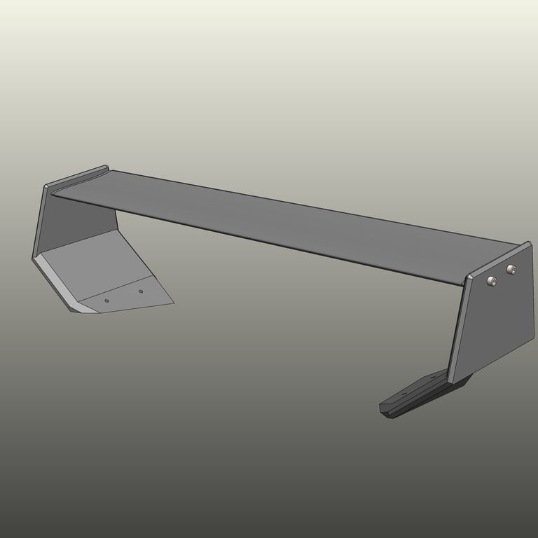


Concept Development & Design Process
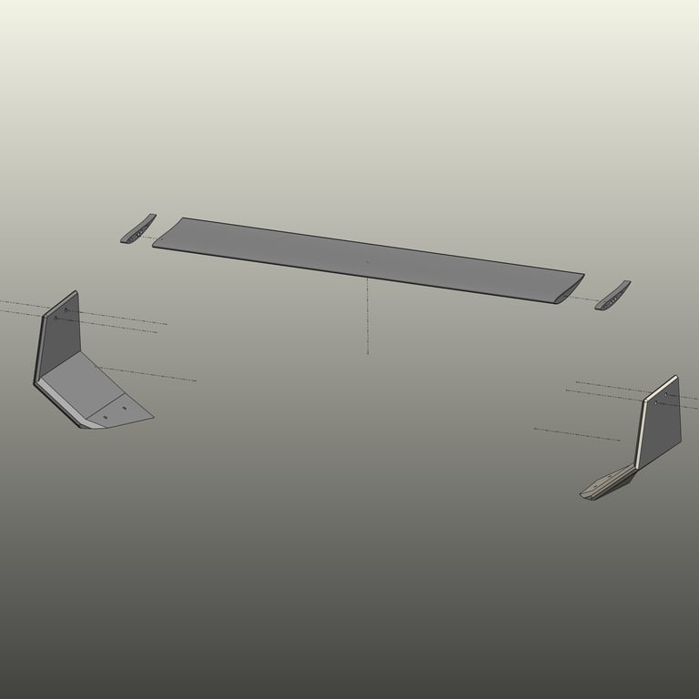
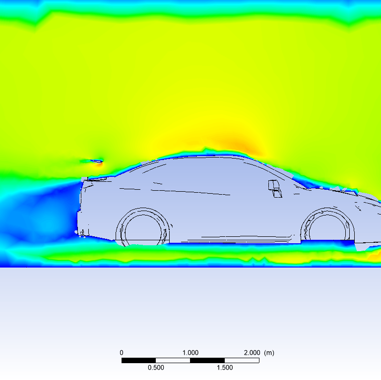
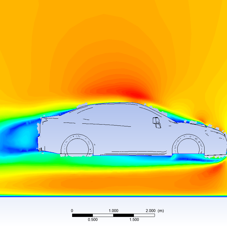
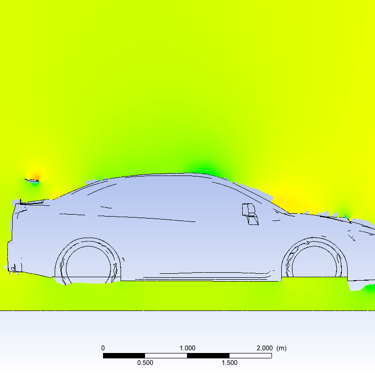
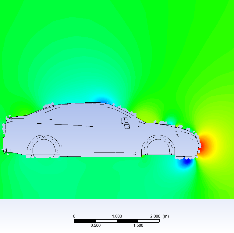
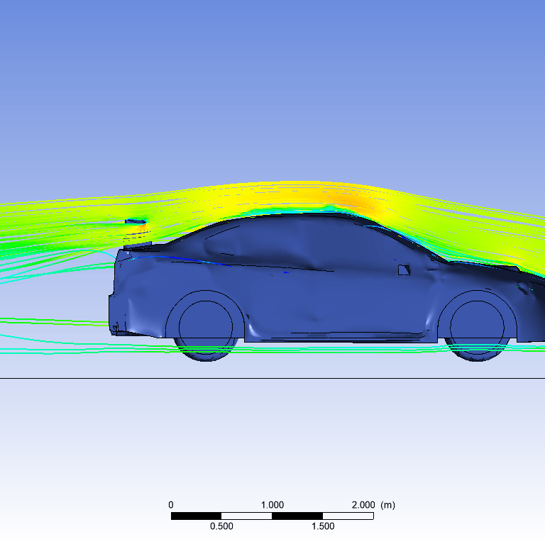
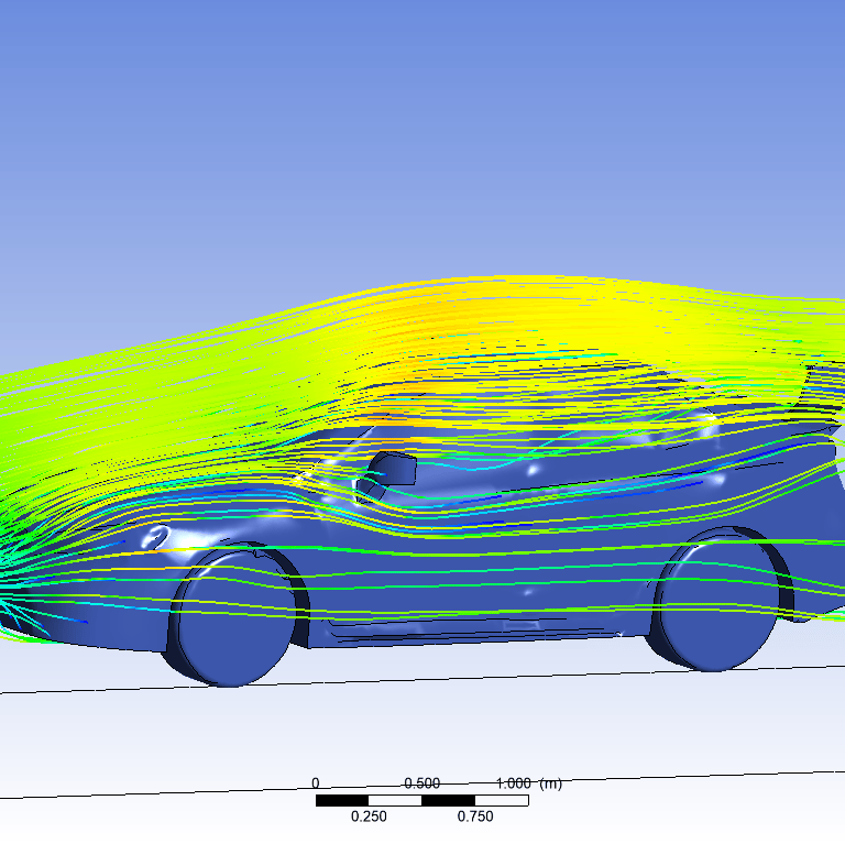
Using SOLIDWORKS, I modeled the wing to optimize airflow characteristics while maintaining compatibility with OEM (Original Equipment Manufacturer) mounting points for the Subaru STI wing. To refine the design, I conducted CFD (Computational Fluid Dynamics) simulations to analyze airflow patterns and pressure distribution, making iterative adjustments to enhance performance. This analysis was performed at 70 MPH, which, relatively speaking, is a lower speed for achieving noticeable aerodynamic effects. However, all simulation plots converged on stable values, indicating reliable results.
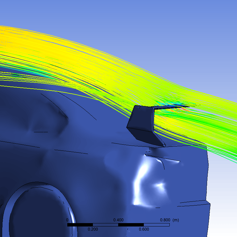
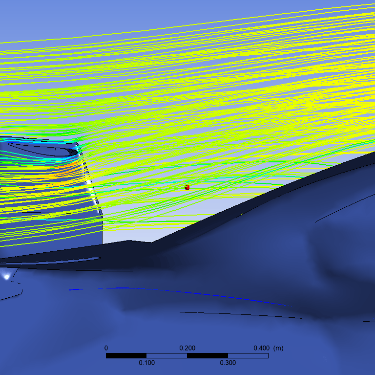
The pressure graphs reveal an increase in pressure above the car with the wing installed, while the pressure beneath the car decreases, generating negative lift (downforce). As speed increases, the wing's effect becomes more pronounced, producing greater rear-end downforce. While the wing does introduce additional drag, it is designed to minimize this effect while maintaining an optimal downforce-to-drag ratio. Velocity distributions appear similar between both configurations, but the wake behind the car with the wing is less compact, suggesting a potential improvement in airflow over the vehicle. However, additional data would be required to confirm this effect.
Another crucial factor is the wing’s placement relative to the rear wheels. Positioning the airfoil further behind the rear axle increases the moment arm acting on the rear wheels. This means that for the same amount of downforce, the increased leverage can exaggerate downforce changes from angle of attack differences, making the front end feel lighter and potentially increasing understeer. Careful consideration of wing placement is essential to balance aerodynamic performance and vehicle handling characteristics.
Prototyping & Fabrication
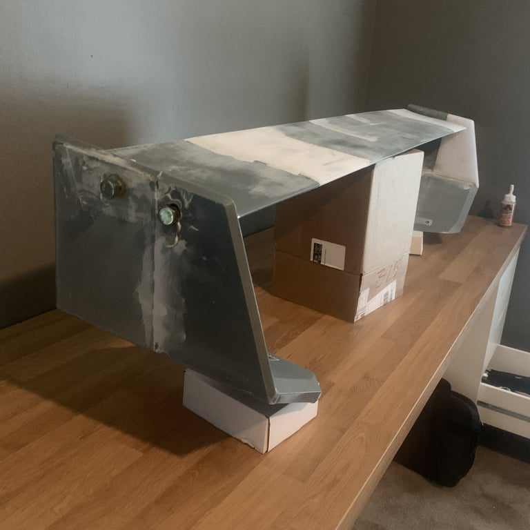
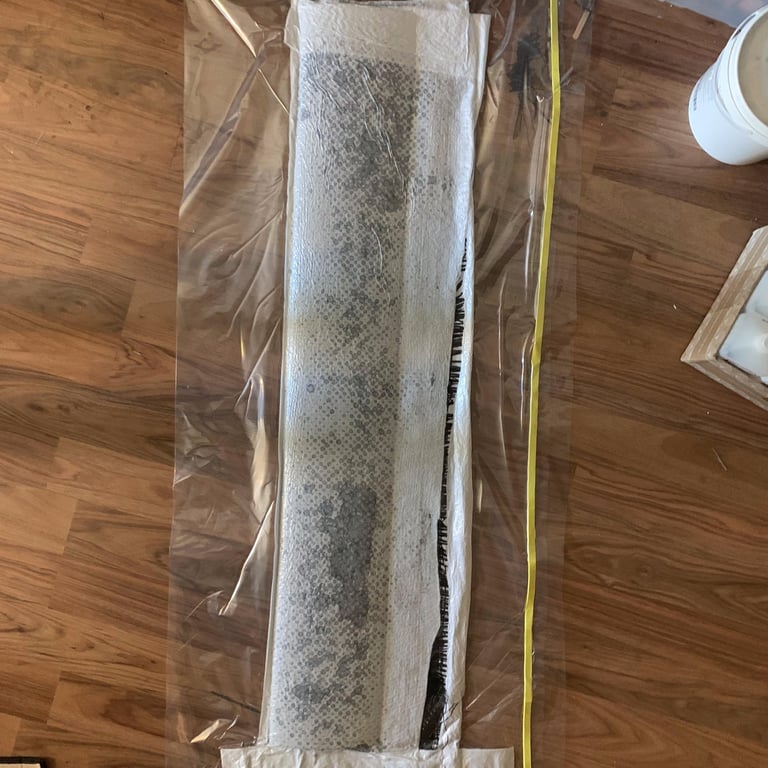
Once the design was finalized, I moved on to prototyping. I began with a 3D-printed model, which was printed in multiple sections and assembled using adhesives to create a full-scale prototype. Once assembled, the structure was skinned with a carbon fiber layup. The layup schedule consisted of two layers of 3K 2x2 twill, a 12K twill, a core material for added structural integrity, followed by another layer of 12K twill, and two final layers of 3K twill. This configuration provided strength in both 45-degree directions, ensuring balanced rigidity throughout the structure. The core material separated the carbon layers, increasing the moment of inertia, which resulted in a stronger part with reduced weight. The use of 12K fabric was intentional, as its increased thickness reduced the number of layers required to achieve the desired structural properties, streamlining the layup process and minimizing labor.
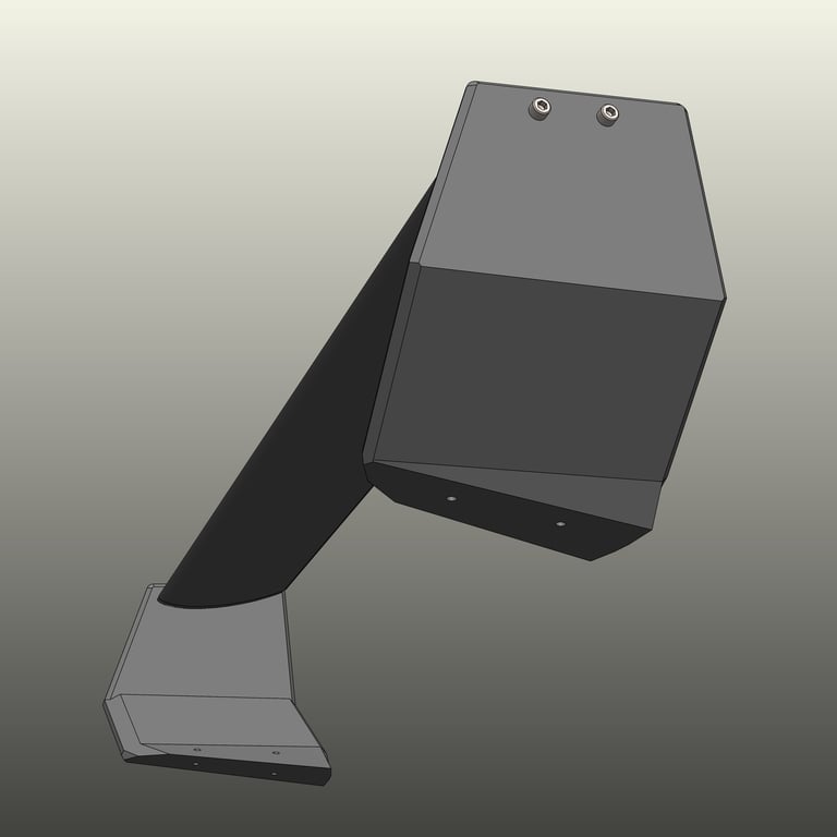
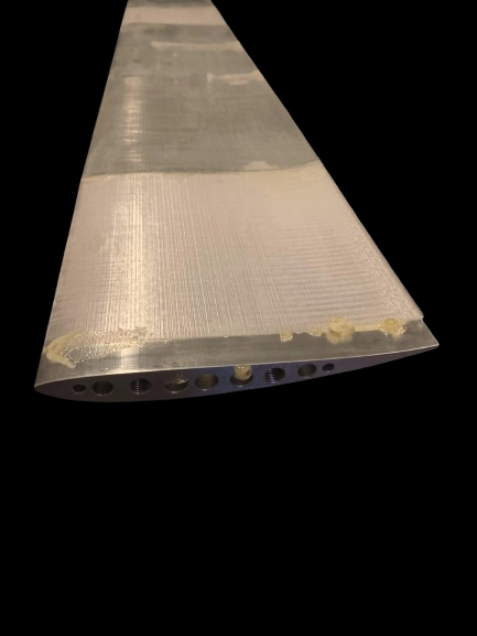
To improve durability, bushings were added to the stabilizers to evenly distribute clamping force from the bolts, preventing localized stress on the plastic or carbon skin. The airfoil section incorporated aluminum end caps that were tapped to accommodate bolts, ensuring a secure and precise assembly. Additionally, the base of the stabilizers featured tapped aluminum inserts, allowing the wing to be securely mounted to the trunk while utilizing the existing STI wing mounting holes for a seamless installation.
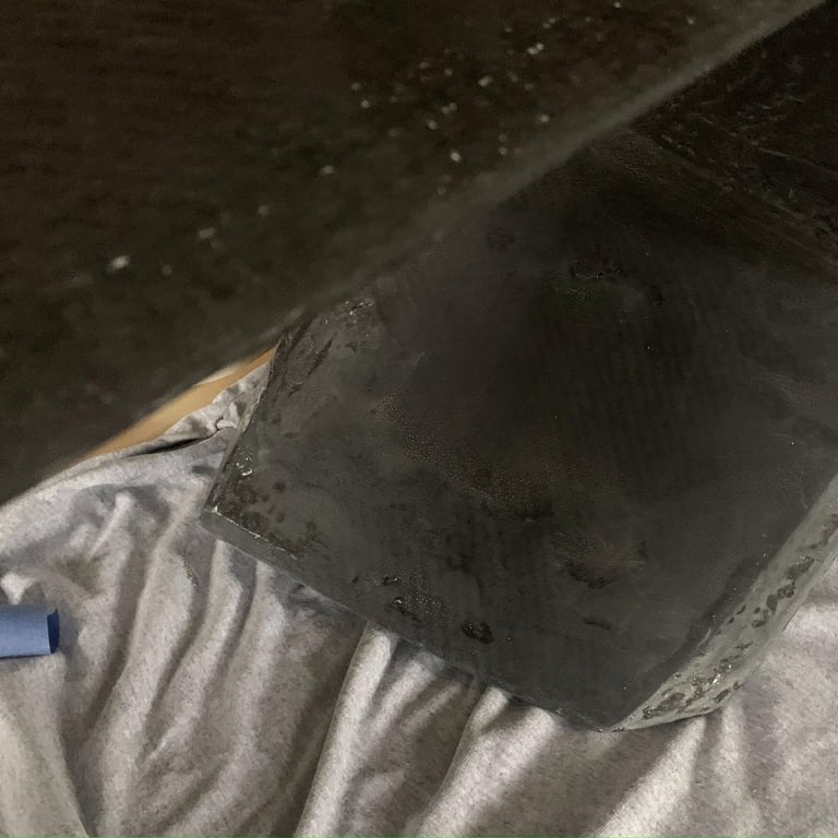
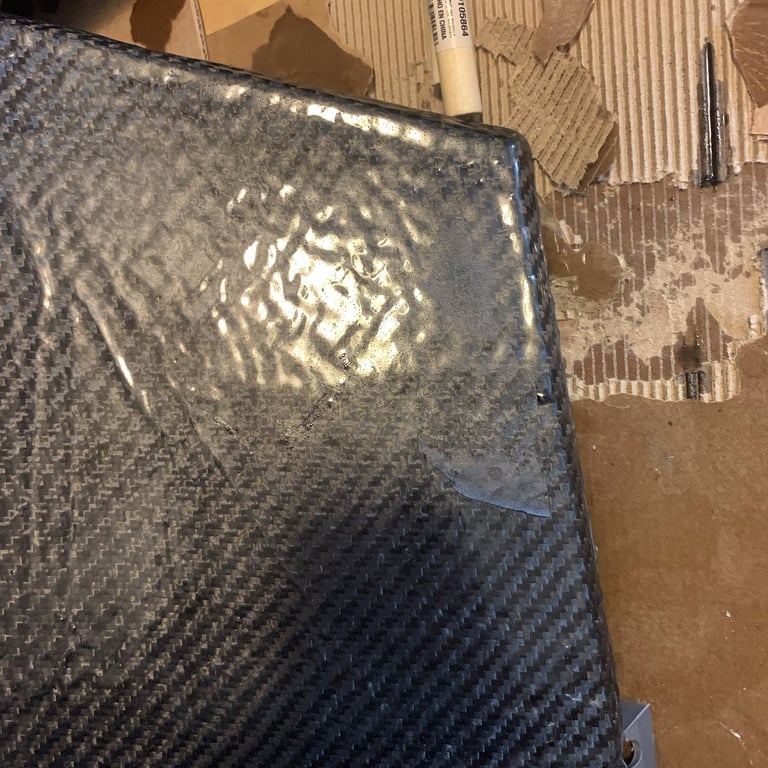
Throughout this process, several challenges arose, particularly in achieving a high-quality surface finish and refining the wet layup technique. Skinning the carbon fiber and executing the wet layup proved more difficult than anticipated, requiring additional resin application to smooth out surface imperfections. The finishing process involved extensive sanding, beginning at 120 grit and progressing through 2000 grit before polishing. Finally, a clear coat was applied to enhance both durability and aesthetics, resulting in a more refined final product.
Testing & Results
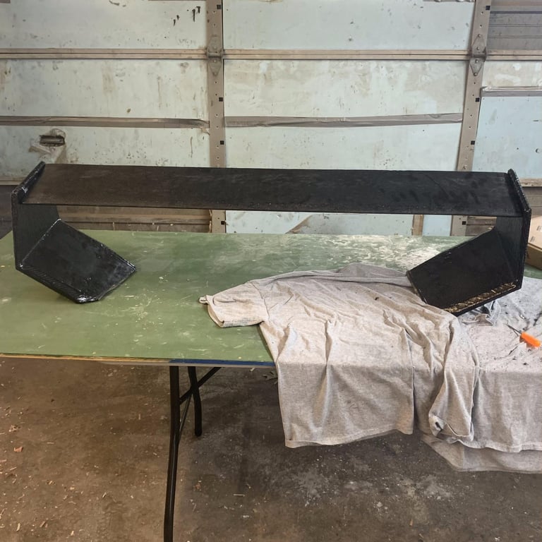
The design works, but as a first prototype, there are many areas for improvement. The manufacturing process is difficult since it is a skinned part, making it challenging to replicate accurately. Additionally, the surface finish is not as refined as I had hoped. The next iteration will incorporate changes to improve the manufacturing process and ensure better consistency. Manufacturing composites is a challenging process upfront, but once the molds are created, production becomes significantly easier and more repeatable.
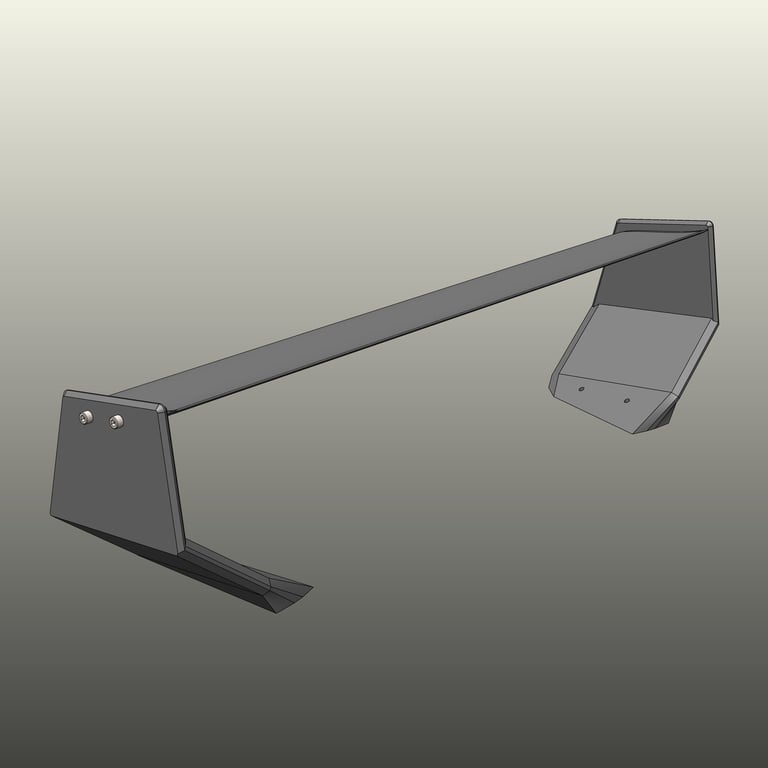
Another area for refinement is the design of the two stabilizers. I believe their aesthetics can be improved, and future posts will showcase the revised designs currently in development.

Final Thoughts
This project represents my passion for engineering and automotive design. It’s a testament to how a well-thought-out design process can turn an idea into a tangible, high-performance product. Stay tuned for updates, and if you're interested in custom aero solutions, feel free to reach out!